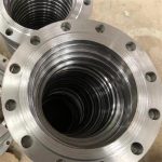
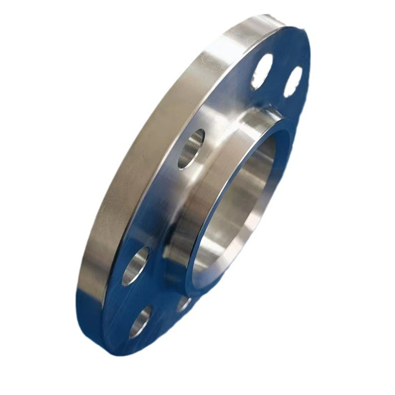
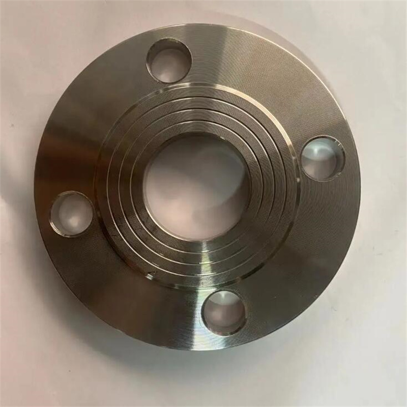
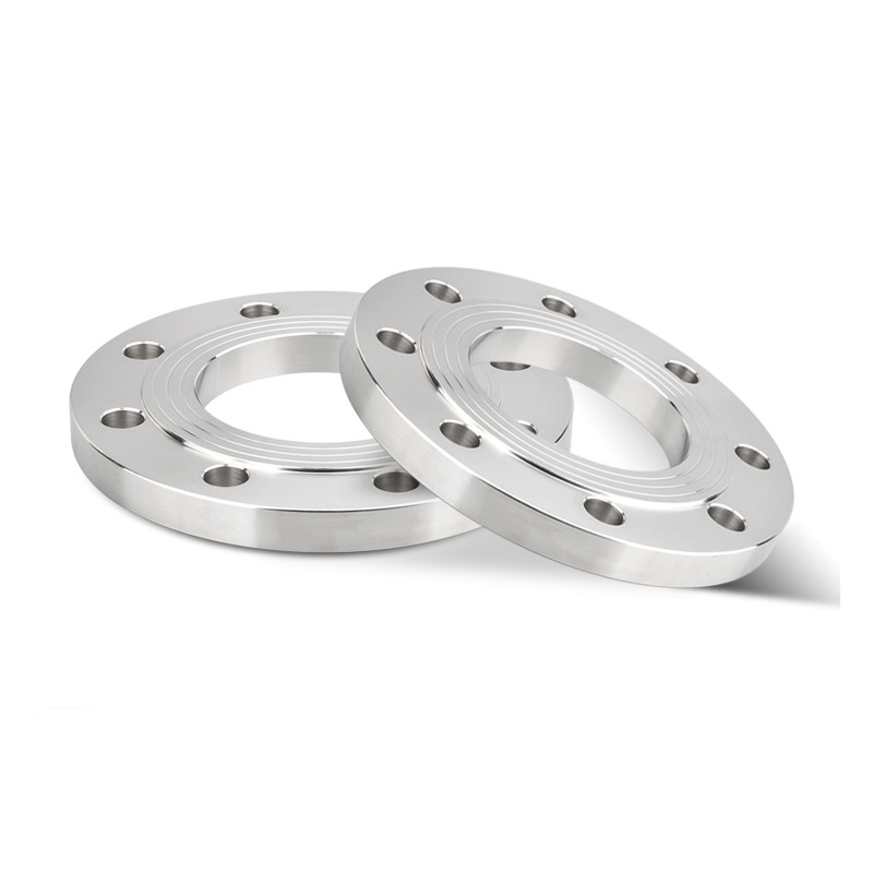
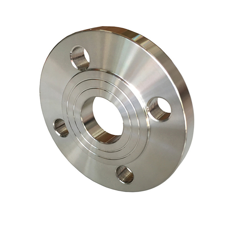
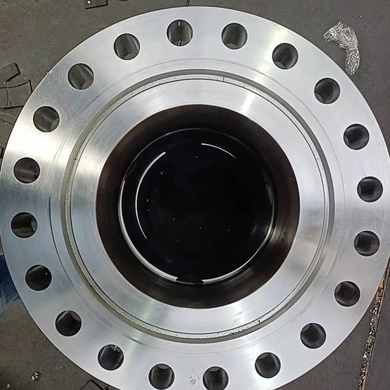
2205 Stainless Steel Flange
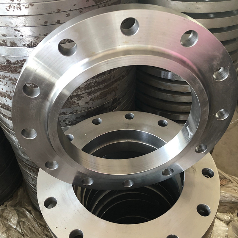
The 2205 stainless steel flange is a type of flange product known for its excellent corrosion resistance and high strength. It is widely used in industries such as chemical processing, oil and gas, and marine applications. Below is a detailed introduction to the 2205 stainless steel flange.
1.Material Features:
(1)The 2205 stainless steel flange is made from duplex stainless steel, which consists of a balanced combination of austenite and ferrite phases.
(2)This material offers exceptional resistance to corrosion, including pitting and crevice corrosion, making it suitable for harsh environments.
(3)It has high strength and toughness, allowing it to withstand heavy loads and impacts.
2.Main Types:
Here are several common types of 2205 stainless steel flanges:
(1)Weld Neck Flange: This flange has a long tapered hub that provides reinforcement and better stress distribution.
(2)Slip-On Flange: This flange slides over the pipe and is then welded in place, offering easy installation and alignment.
(3)Blind Flange: This flange is solid and lacks a bore, primarily used to close off the ends of a piping system.
3.Key Features:
(1)Corrosion Resistance: The 2205 stainless steel flange exhibits superior resistance to various corrosive media, including acids, alkalis, and chlorides.
(2)High Strength: This flange offers excellent strength properties, allowing it to withstand high-pressure and high-temperature conditions.
(3)Duplex Structure: The balanced austenite-ferrite structure provides a combination of properties such as toughness, ductility, and resistance to stress corrosion cracking.
(4)Versatility: The 2205 stainless steel flange is suitable for a wide range of applications, including offshore platforms, chemical processing plants, and pipelines.
4.Application Fields:
The 2205 stainless steel flange finds extensive usage in the following industries:
(1)Chemical Processing: Used in pipelines for handling corrosive chemicals, acids, and solvents.
(2)Oil and Gas: Applied in offshore drilling platforms, subsea pipelines, and other oil and gas exploration and production facilities.
(3)Marine Industry: Utilized in shipbuilding, offshore structures, and marine equipment due to its resistance to seawater corrosion.
| 2205 Stainless Steel Flange Chemical Compositions |
| Grade | C | Mn | P | S | Si | Cr | Ni | Mo | N |
| 2205 | ≤0.03 | ≤2.0 | ≤0.03 | ≤0.02 | ≤1.0 | 22.0-23.0 | 4.5-6.5 | 3.0-3.5 | 0.14-0.20 |
| Parameter | Description |
| Material | 2205 stainless steel |
| Size Range | 1/2 inch - 36 inch |
| Pressure Class | 150 pounds, 300 pounds, 600 pounds |
| Flange Face Type | Raised face (RF), Flat face (FF), Ring type joint (RTJ) |
| Flange Standard | ANSI B16.5, ASME B16.47, DIN, EN, JIS |
| Temperature Range | -50°C to +300°C |
| Suitable Media | Corrosive chemicals, Saltwater, Seawater, Oil and gas, etc. |
| Application Areas | Petrochemical industry, Oil and gas industry, Desalination plants, Water treatment facilities, etc. |

| ANSI, ASME, ASA, B16.5 150lb/sq.in. WELDING NECK FLANGE RF | |||||||||||
| ø | D | b | g | m | a | J* | h | k | Holes | l | Kg. |
| 1/2" | 88,9 | 11,1 | 34,9 | 30,2 | 21,3 | 15,7 | 47,6 | 60,3 | 4 | 15,9 | 0,500 |
| 3/4" | 98,4 | 12,7 | 42,9 | 38,1 | 26,7 | 20,8 | 52,4 | 69,8 | 4 | 15,9 | 0,700 |
| 1" | 107,9 | 14,3 | 50,8 | 49,2 | 33,5 | 26,7 | 55,6 | 79,4 | 4 | 15,9 | 1,100 |
| 1 1/4" | 117,5 | 15,9 | 63,5 | 58,8 | 42,2 | 35,1 | 57,1 | 88,9 | 4 | 15,9 | 1,500 |
| 1 1/2" | 127,0 | 17,5 | 73,0 | 65,1 | 48,3 | 40,9 | 61,9 | 98,4 | 4 | 15,9 | 1,800 |
| 2" | 152,4 | 19,0 | 92,1 | 77,8 | 60,3 | 52,6 | 63,5 | 120,6 | 4 | 19,0 | 2,700 |
| 2 1/2" | 177,8 | 22,2 | 104,8 | 90,5 | 73,1 | 62,7 | 69,8 | 139,7 | 4 | 19,0 | 4,400 |
| 3" | 190,5 | 23,8 | 127,0 | 107,9 | 88,9 | 78,0 | 69,8 | 152,4 | 4 | 19,0 | 5,200 |
| 3 1/2" | 215,9 | 23,8 | 139,7 | 122,2 | 101,6 | 90,2 | 71,4 | 177,8 | 8 | 19,0 | 6,400 |
| 4" | 228,6 | 23,8 | 157,2 | 134,9 | 114,3 | 102,4 | 76,2 | 190,5 | 8 | 19,0 | 7,500 |
| 5" | 254,0 | 23,8 | 185,7 | 163,5 | 141,2 | 128,3 | 88,9 | 215,9 | 8 | 22,2 | 9,200 |
| 6" | 279,4 | 25,4 | 215,9 | 192,1 | 168,4 | 154,2 | 88,9 | 241,3 | 8 | 22,2 | 11,000 |
| 8" | 342,9 | 28,6 | 269,9 | 246,1 | 219,1 | 202,7 | 101,6 | 298,4 | 8 | 22,2 | 18,300 |
| 10" | 406,4 | 30,2 | 323,8 | 304,8 | 273,0 | 254,5 | 101,6 | 361,9 | 12 | 25,4 | 25,000 |
| 12" | 482,6 | 31,7 | 381,0 | 365,1 | 323,8 | 304,8 | 114,3 | 431,8 | 12 | 25,4 | 39,000 |
| 14" | 533,4 | 34,9 | 412,7 | 400,0 | 355,6 | 336,5 | 127,0 | 476,2 | 12 | 28,6 | 51,000 |
| 16" | 596,9 | 36,5 | 469,9 | 457,2 | 406,4 | 387,3 | 127,0 | 539,7 | 16 | 28,6 | 60,000 |
| 18" | 635,0 | 39,7 | 533,4 | 504,8 | 457,2 | 438,1 | 139,7 | 577,8 | 16 | 31,7 | 71,000 |
| 20" | 698,5 | 42,9 | 584,2 | 558,8 | 508,0 | 488,9 | 144,5 | 635,0 | 20 | 31,7 | 88,000 |
| 22" | 749,3 | 46,0 | 641,2 | 609,6 | 558,8 | 539,7 | 149,2 | 692,1 | 20 | 34,9 | 102,000 |
| 24" | 812,8 | 47,6 | 692,1 | 663,6 | 609,6 | 590,5 | 152,4 | 749,3 | 20 | 34,9 | 119,000 |
| *The data "J" corresponds to the STD schedule | |||||||||||
| ANSI, ASME, ASA B16.5 300lb/sq.in. WELDING NECK FLANGE RF | |||||||||||
| ø | D | b | g | m | a | J* | h | k | Holes | l | Kg. |
| 1/2" | 95,2 | 14,3 | 34,9 | 38,1 | 21,3 | 15,7 | 52,4 | 66,7 | 4 | 15,9 | 0,900 |
| 3/4" | 117,5 | 15,9 | 42,9 | 47,6 | 26,7 | 20,8 | 57,1 | 82,5 | 4 | 19,0 | 1,500 |
| 1" | 123,8 | 17,5 | 50,8 | 54,0 | 33,5 | 26,7 | 61,9 | 88,9 | 4 | 19,0 | 1,900 |
| 1 1/4" | 133,3 | 19,0 | 63,5 | 63,5 | 42,2 | 35,1 | 65,1 | 98,4 | 4 | 19,0 | 2,600 |
| 1 1/2" | 155,6 | 20,6 | 73,0 | 69,8 | 48,3 | 40,9 | 68,3 | 114,3 | 4 | 22,2 | 3,300 |
| 2" | 165,1 | 22,2 | 92,1 | 84,1 | 60,3 | 52,6 | 69,8 | 127,0 | 8 | 19,0 | 3,600 |
| 2 1/2" | 190,5 | 25,4 | 104,8 | 100,0 | 73,1 | 62,7 | 76,2 | 149,2 | 8 | 22,2 | 5,400 |
| 3" | 209,5 | 28,6 | 127,0 | 117,5 | 88,9 | 78,0 | 79,4 | 168,3 | 8 | 22,2 | 7,400 |
| 3 1/2" | 228,6 | 30,2 | 139,7 | 133,3 | 101,6 | 90,2 | 81,0 | 184,1 | 8 | 22,2 | 8,900 |
| 4" | 254,0 | 31,7 | 157,2 | 146,0 | 114,3 | 102,4 | 85,7 | 200,0 | 8 | 22,2 | 11,900 |
| 5" | 279,4 | 34,9 | 185,7 | 177,8 | 141,2 | 128,3 | 98,4 | 234,9 | 8 | 22,2 | 16,000 |
| 6" | 317,5 | 36,5 | 215,9 | 206,4 | 168,4 | 154,2 | 98,4 | 269,9 | 12 | 22,2 | 20,200 |
| 8" | 381,0 | 41,3 | 269,9 | 260,3 | 219,1 | 202,7 | 111,1 | 330,2 | 12 | 25,4 | 31,000 |
| 10" | 444,5 | 47,6 | 323,4 | 320,7 | 273,0 | 254,5 | 117,5 | 387,3 | 16 | 28,6 | 44,300 |
| 12" | 520,7 | 50,8 | 381,0 | 374,6 | 323,8 | 304,8 | 130,2 | 450,8 | 16 | 31,7 | 64,000 |
| 14" | 584,2 | 54,0 | 412,7 | 425,4 | 355,6 | 336,5 | 142,9 | 514,3 | 20 | 31,7 | 88,000 |
| 16" | 647,7 | 57,1 | 469,9 | 482,6 | 406,4 | 387,3 | 146,0 | 571,5 | 20 | 34,9 | 113,000 |
| 18" | 711,2 | 60,3 | 533,4 | 533,4 | 457,2 | 438,1 | 158,7 | 628,6 | 24 | 34,9 | 134,000 |
| 20" | 774,7 | 63,5 | 584,2 | 587,4 | 508,0 | 488,9 | 161,9 | 685,8 | 24 | 34,9 | 171,000 |
| 22" | 838,2 | 66,7 | 641,2 | 641,2 | 558,8 | 539,7 | 165,1 | 742,9 | 24 | 41,3 | 195,000 |
| 24" | 914,4 | 69,8 | 692,1 | 701,7 | 609,6 | 590,5 | 168,3 | 812,8 | 24 | 41,3 | 238,000 |
| *The data "J" corresponds to the STD schedule | |||||||||||
| ANSI/ASME/ASA B16.5 600lb/sq.in. WELDING NECK FLANGE RF | |||||||||||
| ø | D | b | g | m | a | J* | h | k | Holes | l | Kg. |
| 1/2" | 95,2 | 14,3 | 34,9 | 38,1 | 21,3 | 15,7 | 52,4 | 66,7 | 4 | 15,9 | 0,900 |
| 3/4" | 117,5 | 15,9 | 42,9 | 47,6 | 26,7 | 20,9 | 57,1 | 82,5 | 4 | 19,0 | 1,500 |
| 1" | 123,8 | 17,5 | 50,8 | 54,0 | 33,5 | 26,7 | 61,9 | 88,9 | 4 | 19,0 | 1,900 |
| 1 1/4" | 133,3 | 20,6 | 63,5 | 63,5 | 42,2 | 35,0 | 66,7 | 98,4 | 4 | 19,0 | 2,600 |
| 1 1/2" | 155,6 | 22,2 | 73,0 | 69,8 | 48,3 | 40,9 | 69,8 | 114,3 | 4 | 22,2 | 3,300 |
| 2" | 165,1 | 25,4 | 92,1 | 84,1 | 60,3 | 52,6 | 73,0 | 127,0 | 8 | 19,0 | 4,700 |
| 2 1/2" | 190,5 | 28,6 | 104,8 | 100,0 | 73,1 | 62,7 | 79,4 | 149,2 | 8 | 22,2 | 6,500 |
| 3" | 209,5 | 31,7 | 127,0 | 117,5 | 88,9 | 78,0 | 82,5 | 168,3 | 8 | 22,2 | 8,700 |
| 3 1/2" | 228,6 | 34,9 | 139,7 | 133,3 | 101,6 | 90,1 | 85,7 | 184,1 | 8 | 25,4 | 11,200 |
| 4" | 273,0 | 38,1 | 157,2 | 152,4 | 114,3 | 102,4 | 101,6 | 215,9 | 8 | 25,4 | 18,100 |
| 5" | 330,2 | 44,4 | 185,7 | 188,9 | 141,2 | 128,2 | 114,3 | 266,7 | 8 | 28,6 | 30,500 |
| 6" | 355,6 | 47,6 | 215,9 | 222,2 | 168,4 | 154,2 | 117,5 | 292,1 | 12 | 28,6 | 36,200 |
| 8" | 419,1 | 55,6 | 269,9 | 273,0 | 219,1 | 202,7 | 133,3 | 349,2 | 12 | 31,7 | 56,500 |
| 10" | 508,0 | 63,5 | 323,8 | 342,9 | 273,0 | 254,5 | 152,4 | 431,8 | 16 | 34,9 | 91,000 |
| 12" | 558,8 | 66,7 | 381,0 | 400,0 | 323,8 | 304,8 | 155,6 | 488,9 | 20 | 34,9 | 105,000 |
| 14" | 603,2 | 69,8 | 412,7 | 431,8 | 355,6 | * | 165,1 | 527,0 | 20 | 38,1 | 125,000 |
| 16" | 685,8 | 76,2 | 469,9 | 495,3 | 406,4 | 177,8 | 603,2 | 20 | 41,3 | 178,000 | |
| 18" | 742,9 | 82,5 | 533,4 | 546,1 | 457,2 | 184,1 | 654,0 | 20 | 44,4 | 261,000 | |
| 20" | 812,8 | 88,9 | 584,2 | 609,6 | 508,0 | 190,5 | 723,9 | 24 | 44,4 | 268,000 | |
| 22" | 869,9 | 95,2 | 641,2 | 666,7 | 558,8 | 196,8 | 777,9 | 24 | 47,6 | 328,000 | |
| 24" | 939,8 | 101,6 | 692,1 | 717,5 | 609,6 | 203,2 | 838,2 | 24 | 50,8 | 380,000 | |
| *The data "J" corresponds to the STD schedule | |||||||||||
| To be specifiedby customer | |||||||||||

