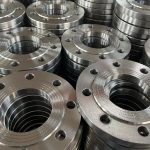
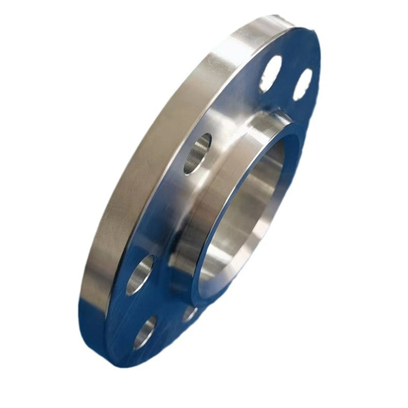
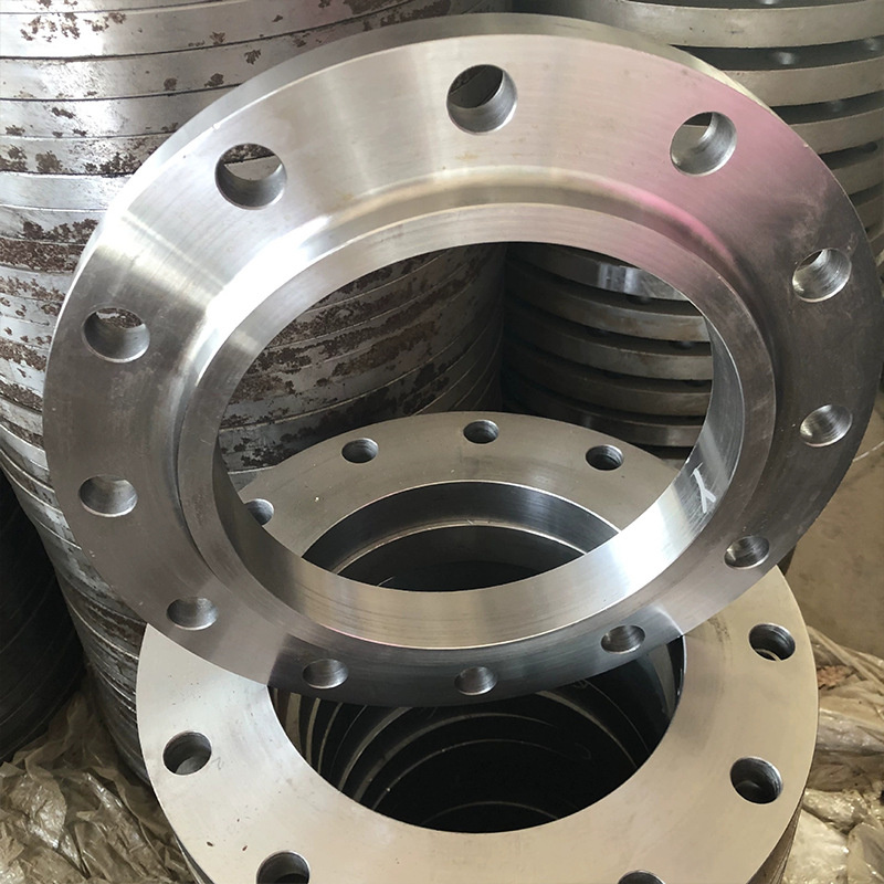
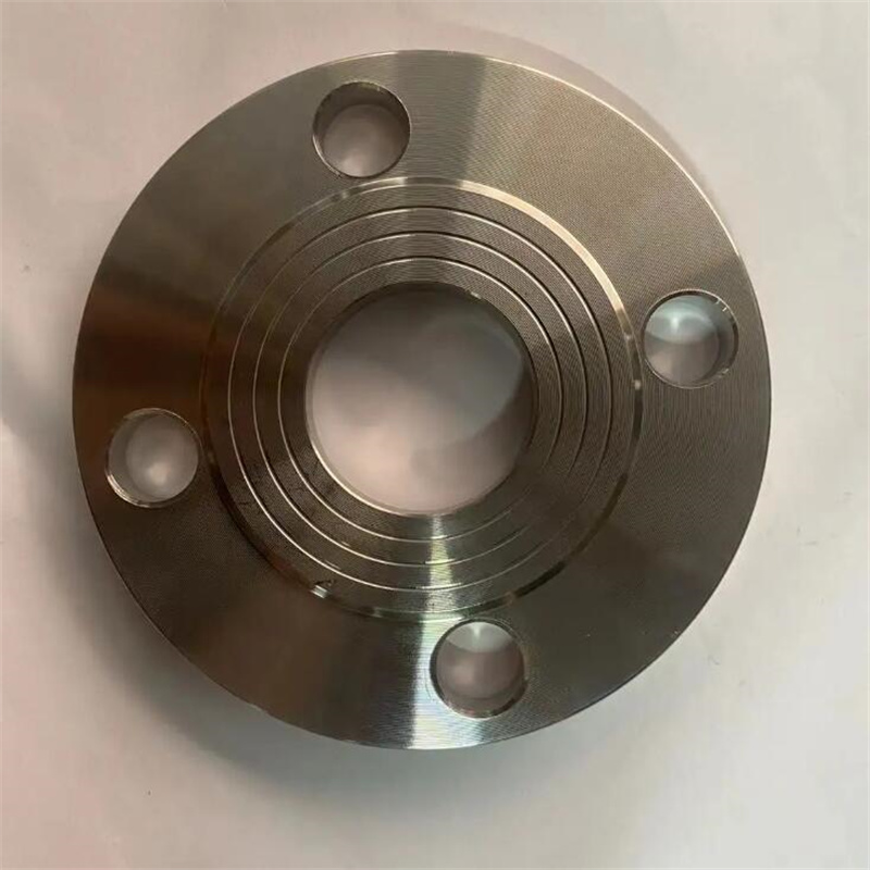
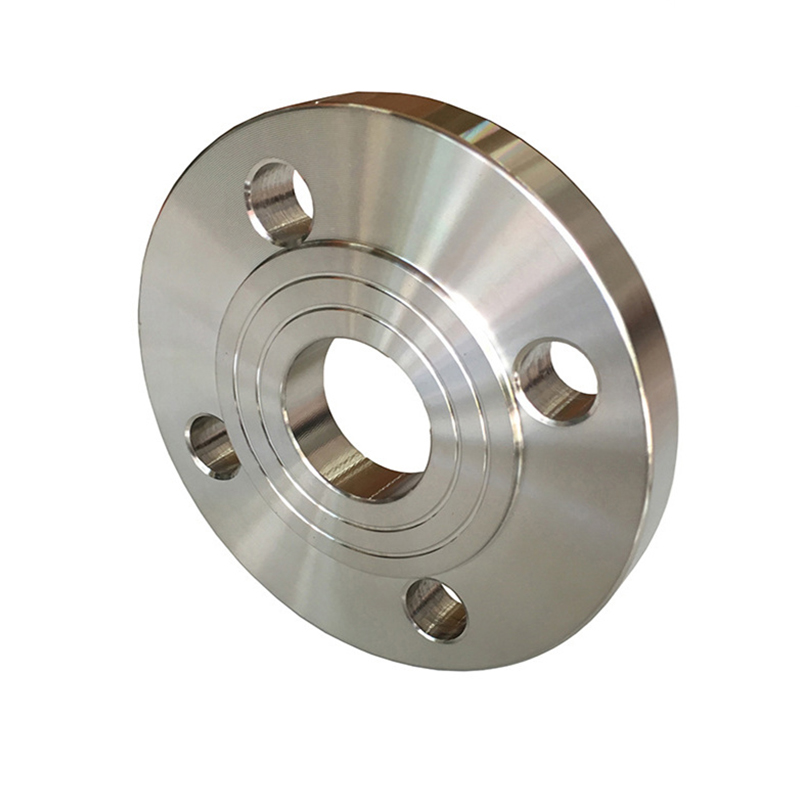
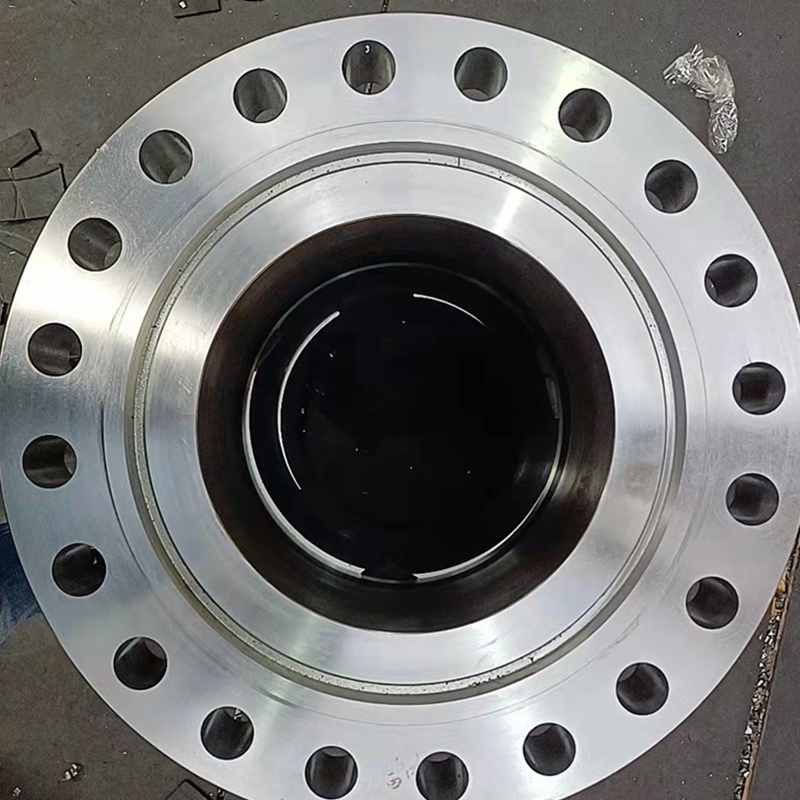
254 Stainless Steel Flange
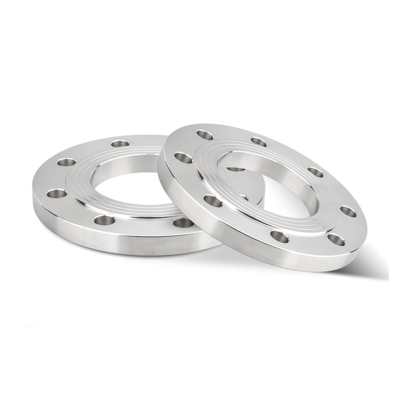
The 254 stainless steel flange is a high-strength and corrosion-resistant flange product. Due to its excellent performance in high-temperature and corrosive environments, it is widely used in fields such as chemical, petroleum, and aerospace. The following is a detailed introduction to the 254 stainless steel flange.
1.Material Features:
(1)The 254 stainless steel flange is made of high-quality stainless steel material, mainly composed of nickel, chromium, molybdenum, and copper, offering outstanding corrosion resistance.
(2)This stainless steel material can maintain good mechanical properties under extreme conditions, including high temperature, high pressure, and acidic or alkaline environments.
2.Main Types:
Here are several common types of 254 stainless steel flanges:
(1)Forged Flange: Made by forging the 254 stainless steel, it has high strength and reliable connection performance.
(2)Welding Flange: Assembled by welding techniques to combine 254 stainless steel components, achieving sealed connections under appropriate process conditions.
(3)Bolted Flange: Connected with other flanges or pipes using bolts, facilitating disassembly and maintenance.
3.Key Features:
(1)Excellent Corrosion Resistance: The 254 stainless steel flange exhibits exceptional resistance against oxidation, acid attack, alkali corrosion, and other chemical substances.
(2)High-Temperature Stability: This material maintains stability under high-temperature conditions, resisting deformation or damage.
(3)Strength and Pressure Resistance: The 254 stainless steel flange possesses good strength and pressure resistance, capable of withstanding high-pressure working conditions.
(4)Reliable Sealing Performance: With suitable sealing structures, the 254 stainless steel flange ensures dependable sealing, preventing leakage issues.
4.Application Fields:
Due to its superior performance, the 254 stainless steel flange is widely used in the following industries:
(1)Chemical Industry: Used for chemical transportation and processing systems, including conveying acid and alkali liquids, solvents, and corrosive gases.
(2)Oil and Gas Industry: Applied in oil refining, petrochemical, and natural gas processing, connecting pipelines in various fields.
(3)Aerospace Industry: Utilized in aircraft exhaust systems, fuel systems, and hydraulic systems for reliable connections.
| 254 Stainless Steel Flange Chemical Compositions |
| Grade | C | Mn | P | S | Si | Cr | Ni | Mo | Cu | N |
| 254 | ≤0.02 | ≤1.0 | ≤0.02 | ≤0.01 | ≤0.7 | 19.5-20.5 | 17.5-18.5 | 6.0-6.5 | 0.5-1.0 | ≤0.02 |
| Parameter | Description |
| Material | 254 stainless steel |
| Size Range | 1/2 inch - 36 inch |
| Pressure Class | 150 pounds, 300 pounds, 600 pounds |
| Flange Face Type | Raised face (RF), Flat face (FF), Ring type joint (RTJ) |
| Flange Standard | ANSI B16.5, ASME B16.47, DIN, EN, JIS |
| Temperature Range | -200°C to +550°C |
| Suitable Media | Corrosive chemicals, Acids, Saltwater, Seawater, etc. |
| Application Areas | Chemical industry, Marine industry, Oil and gas industry, Pulp and paper industry, etc. |

| ANSI, ASME, ASA, B16.5 150lb/sq.in. WELDING NECK FLANGE RF | |||||||||||
| ø | D | b | g | m | a | J* | h | k | Holes | l | Kg. |
| 1/2" | 88,9 | 11,1 | 34,9 | 30,2 | 21,3 | 15,7 | 47,6 | 60,3 | 4 | 15,9 | 0,500 |
| 3/4" | 98,4 | 12,7 | 42,9 | 38,1 | 26,7 | 20,8 | 52,4 | 69,8 | 4 | 15,9 | 0,700 |
| 1" | 107,9 | 14,3 | 50,8 | 49,2 | 33,5 | 26,7 | 55,6 | 79,4 | 4 | 15,9 | 1,100 |
| 1 1/4" | 117,5 | 15,9 | 63,5 | 58,8 | 42,2 | 35,1 | 57,1 | 88,9 | 4 | 15,9 | 1,500 |
| 1 1/2" | 127,0 | 17,5 | 73,0 | 65,1 | 48,3 | 40,9 | 61,9 | 98,4 | 4 | 15,9 | 1,800 |
| 2" | 152,4 | 19,0 | 92,1 | 77,8 | 60,3 | 52,6 | 63,5 | 120,6 | 4 | 19,0 | 2,700 |
| 2 1/2" | 177,8 | 22,2 | 104,8 | 90,5 | 73,1 | 62,7 | 69,8 | 139,7 | 4 | 19,0 | 4,400 |
| 3" | 190,5 | 23,8 | 127,0 | 107,9 | 88,9 | 78,0 | 69,8 | 152,4 | 4 | 19,0 | 5,200 |
| 3 1/2" | 215,9 | 23,8 | 139,7 | 122,2 | 101,6 | 90,2 | 71,4 | 177,8 | 8 | 19,0 | 6,400 |
| 4" | 228,6 | 23,8 | 157,2 | 134,9 | 114,3 | 102,4 | 76,2 | 190,5 | 8 | 19,0 | 7,500 |
| 5" | 254,0 | 23,8 | 185,7 | 163,5 | 141,2 | 128,3 | 88,9 | 215,9 | 8 | 22,2 | 9,200 |
| 6" | 279,4 | 25,4 | 215,9 | 192,1 | 168,4 | 154,2 | 88,9 | 241,3 | 8 | 22,2 | 11,000 |
| 8" | 342,9 | 28,6 | 269,9 | 246,1 | 219,1 | 202,7 | 101,6 | 298,4 | 8 | 22,2 | 18,300 |
| 10" | 406,4 | 30,2 | 323,8 | 304,8 | 273,0 | 254,5 | 101,6 | 361,9 | 12 | 25,4 | 25,000 |
| 12" | 482,6 | 31,7 | 381,0 | 365,1 | 323,8 | 304,8 | 114,3 | 431,8 | 12 | 25,4 | 39,000 |
| 14" | 533,4 | 34,9 | 412,7 | 400,0 | 355,6 | 336,5 | 127,0 | 476,2 | 12 | 28,6 | 51,000 |
| 16" | 596,9 | 36,5 | 469,9 | 457,2 | 406,4 | 387,3 | 127,0 | 539,7 | 16 | 28,6 | 60,000 |
| 18" | 635,0 | 39,7 | 533,4 | 504,8 | 457,2 | 438,1 | 139,7 | 577,8 | 16 | 31,7 | 71,000 |
| 20" | 698,5 | 42,9 | 584,2 | 558,8 | 508,0 | 488,9 | 144,5 | 635,0 | 20 | 31,7 | 88,000 |
| 22" | 749,3 | 46,0 | 641,2 | 609,6 | 558,8 | 539,7 | 149,2 | 692,1 | 20 | 34,9 | 102,000 |
| 24" | 812,8 | 47,6 | 692,1 | 663,6 | 609,6 | 590,5 | 152,4 | 749,3 | 20 | 34,9 | 119,000 |
| *The data "J" corresponds to the STD schedule | |||||||||||
| ANSI, ASME, ASA B16.5 300lb/sq.in. WELDING NECK FLANGE RF | |||||||||||
| ø | D | b | g | m | a | J* | h | k | Holes | l | Kg. |
| 1/2" | 95,2 | 14,3 | 34,9 | 38,1 | 21,3 | 15,7 | 52,4 | 66,7 | 4 | 15,9 | 0,900 |
| 3/4" | 117,5 | 15,9 | 42,9 | 47,6 | 26,7 | 20,8 | 57,1 | 82,5 | 4 | 19,0 | 1,500 |
| 1" | 123,8 | 17,5 | 50,8 | 54,0 | 33,5 | 26,7 | 61,9 | 88,9 | 4 | 19,0 | 1,900 |
| 1 1/4" | 133,3 | 19,0 | 63,5 | 63,5 | 42,2 | 35,1 | 65,1 | 98,4 | 4 | 19,0 | 2,600 |
| 1 1/2" | 155,6 | 20,6 | 73,0 | 69,8 | 48,3 | 40,9 | 68,3 | 114,3 | 4 | 22,2 | 3,300 |
| 2" | 165,1 | 22,2 | 92,1 | 84,1 | 60,3 | 52,6 | 69,8 | 127,0 | 8 | 19,0 | 3,600 |
| 2 1/2" | 190,5 | 25,4 | 104,8 | 100,0 | 73,1 | 62,7 | 76,2 | 149,2 | 8 | 22,2 | 5,400 |
| 3" | 209,5 | 28,6 | 127,0 | 117,5 | 88,9 | 78,0 | 79,4 | 168,3 | 8 | 22,2 | 7,400 |
| 3 1/2" | 228,6 | 30,2 | 139,7 | 133,3 | 101,6 | 90,2 | 81,0 | 184,1 | 8 | 22,2 | 8,900 |
| 4" | 254,0 | 31,7 | 157,2 | 146,0 | 114,3 | 102,4 | 85,7 | 200,0 | 8 | 22,2 | 11,900 |
| 5" | 279,4 | 34,9 | 185,7 | 177,8 | 141,2 | 128,3 | 98,4 | 234,9 | 8 | 22,2 | 16,000 |
| 6" | 317,5 | 36,5 | 215,9 | 206,4 | 168,4 | 154,2 | 98,4 | 269,9 | 12 | 22,2 | 20,200 |
| 8" | 381,0 | 41,3 | 269,9 | 260,3 | 219,1 | 202,7 | 111,1 | 330,2 | 12 | 25,4 | 31,000 |
| 10" | 444,5 | 47,6 | 323,4 | 320,7 | 273,0 | 254,5 | 117,5 | 387,3 | 16 | 28,6 | 44,300 |
| 12" | 520,7 | 50,8 | 381,0 | 374,6 | 323,8 | 304,8 | 130,2 | 450,8 | 16 | 31,7 | 64,000 |
| 14" | 584,2 | 54,0 | 412,7 | 425,4 | 355,6 | 336,5 | 142,9 | 514,3 | 20 | 31,7 | 88,000 |
| 16" | 647,7 | 57,1 | 469,9 | 482,6 | 406,4 | 387,3 | 146,0 | 571,5 | 20 | 34,9 | 113,000 |
| 18" | 711,2 | 60,3 | 533,4 | 533,4 | 457,2 | 438,1 | 158,7 | 628,6 | 24 | 34,9 | 134,000 |
| 20" | 774,7 | 63,5 | 584,2 | 587,4 | 508,0 | 488,9 | 161,9 | 685,8 | 24 | 34,9 | 171,000 |
| 22" | 838,2 | 66,7 | 641,2 | 641,2 | 558,8 | 539,7 | 165,1 | 742,9 | 24 | 41,3 | 195,000 |
| 24" | 914,4 | 69,8 | 692,1 | 701,7 | 609,6 | 590,5 | 168,3 | 812,8 | 24 | 41,3 | 238,000 |
| *The data "J" corresponds to the STD schedule | |||||||||||
| ANSI/ASME/ASA B16.5 600lb/sq.in. WELDING NECK FLANGE RF | |||||||||||
| ø | D | b | g | m | a | J* | h | k | Holes | l | Kg. |
| 1/2" | 95,2 | 14,3 | 34,9 | 38,1 | 21,3 | 15,7 | 52,4 | 66,7 | 4 | 15,9 | 0,900 |
| 3/4" | 117,5 | 15,9 | 42,9 | 47,6 | 26,7 | 20,9 | 57,1 | 82,5 | 4 | 19,0 | 1,500 |
| 1" | 123,8 | 17,5 | 50,8 | 54,0 | 33,5 | 26,7 | 61,9 | 88,9 | 4 | 19,0 | 1,900 |
| 1 1/4" | 133,3 | 20,6 | 63,5 | 63,5 | 42,2 | 35,0 | 66,7 | 98,4 | 4 | 19,0 | 2,600 |
| 1 1/2" | 155,6 | 22,2 | 73,0 | 69,8 | 48,3 | 40,9 | 69,8 | 114,3 | 4 | 22,2 | 3,300 |
| 2" | 165,1 | 25,4 | 92,1 | 84,1 | 60,3 | 52,6 | 73,0 | 127,0 | 8 | 19,0 | 4,700 |
| 2 1/2" | 190,5 | 28,6 | 104,8 | 100,0 | 73,1 | 62,7 | 79,4 | 149,2 | 8 | 22,2 | 6,500 |
| 3" | 209,5 | 31,7 | 127,0 | 117,5 | 88,9 | 78,0 | 82,5 | 168,3 | 8 | 22,2 | 8,700 |
| 3 1/2" | 228,6 | 34,9 | 139,7 | 133,3 | 101,6 | 90,1 | 85,7 | 184,1 | 8 | 25,4 | 11,200 |
| 4" | 273,0 | 38,1 | 157,2 | 152,4 | 114,3 | 102,4 | 101,6 | 215,9 | 8 | 25,4 | 18,100 |
| 5" | 330,2 | 44,4 | 185,7 | 188,9 | 141,2 | 128,2 | 114,3 | 266,7 | 8 | 28,6 | 30,500 |
| 6" | 355,6 | 47,6 | 215,9 | 222,2 | 168,4 | 154,2 | 117,5 | 292,1 | 12 | 28,6 | 36,200 |
| 8" | 419,1 | 55,6 | 269,9 | 273,0 | 219,1 | 202,7 | 133,3 | 349,2 | 12 | 31,7 | 56,500 |
| 10" | 508,0 | 63,5 | 323,8 | 342,9 | 273,0 | 254,5 | 152,4 | 431,8 | 16 | 34,9 | 91,000 |
| 12" | 558,8 | 66,7 | 381,0 | 400,0 | 323,8 | 304,8 | 155,6 | 488,9 | 20 | 34,9 | 105,000 |
| 14" | 603,2 | 69,8 | 412,7 | 431,8 | 355,6 | * | 165,1 | 527,0 | 20 | 38,1 | 125,000 |
| 16" | 685,8 | 76,2 | 469,9 | 495,3 | 406,4 | 177,8 | 603,2 | 20 | 41,3 | 178,000 | |
| 18" | 742,9 | 82,5 | 533,4 | 546,1 | 457,2 | 184,1 | 654,0 | 20 | 44,4 | 261,000 | |
| 20" | 812,8 | 88,9 | 584,2 | 609,6 | 508,0 | 190,5 | 723,9 | 24 | 44,4 | 268,000 | |
| 22" | 869,9 | 95,2 | 641,2 | 666,7 | 558,8 | 196,8 | 777,9 | 24 | 47,6 | 328,000 | |
| 24" | 939,8 | 101,6 | 692,1 | 717,5 | 609,6 | 203,2 | 838,2 | 24 | 50,8 | 380,000 | |
| *The data "J" corresponds to the STD schedule | |||||||||||
| To be specifiedby customer | |||||||||||

