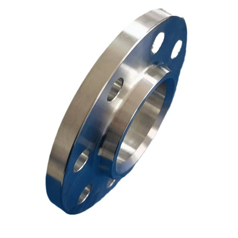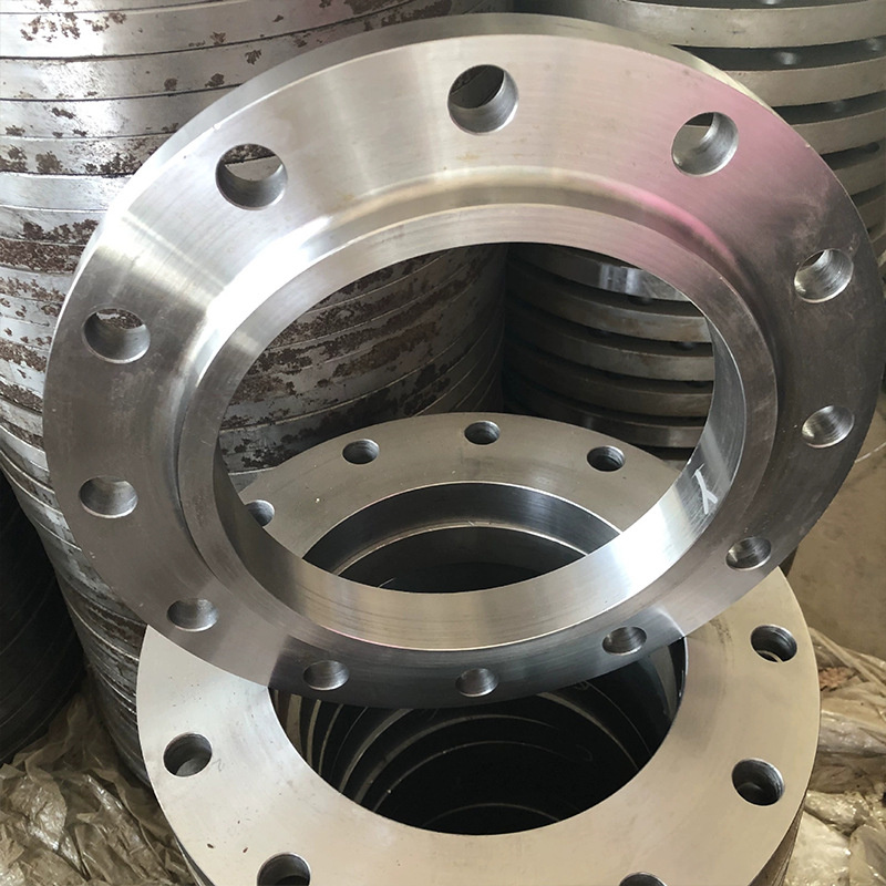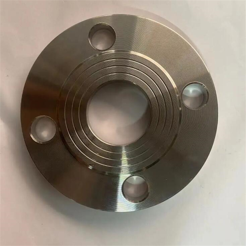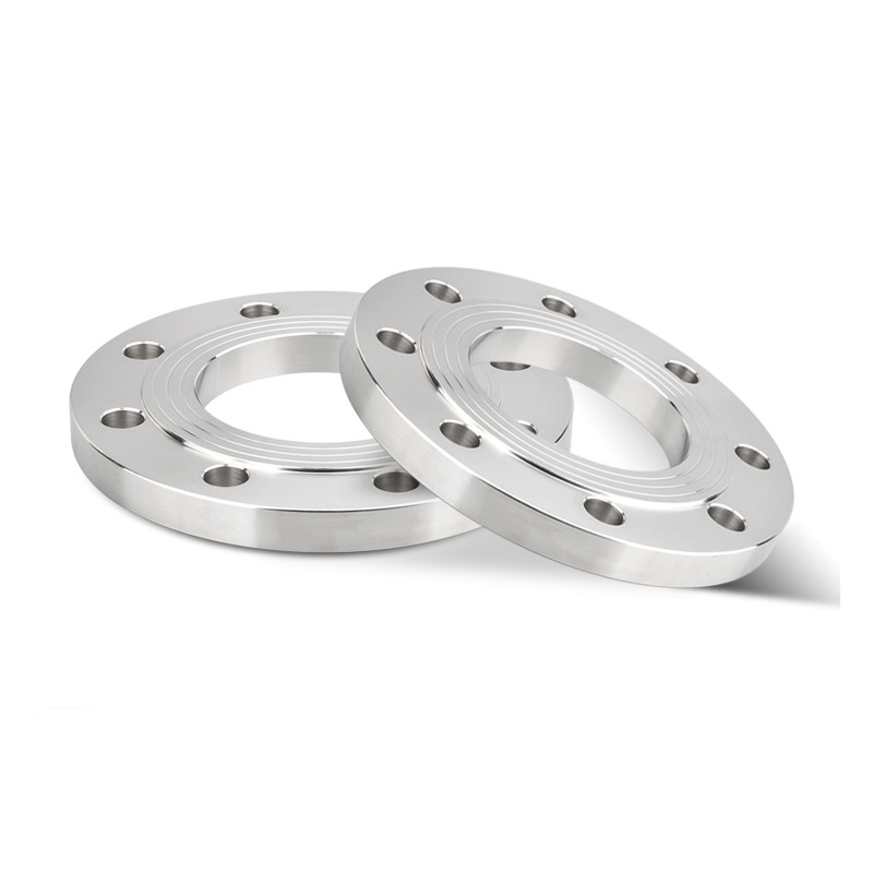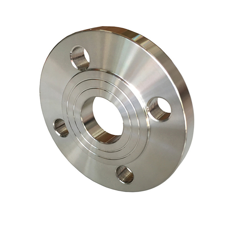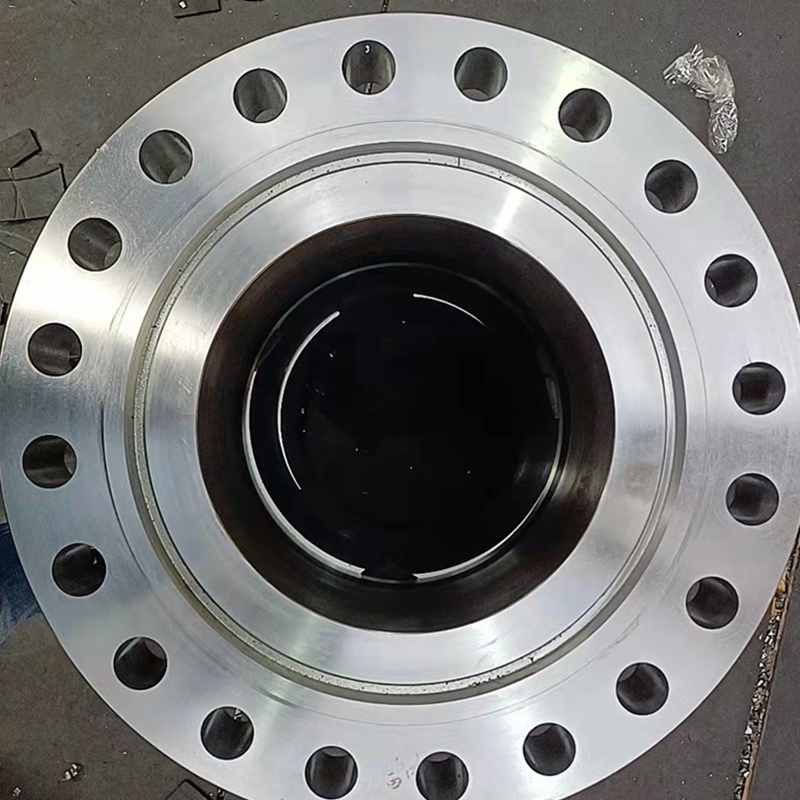
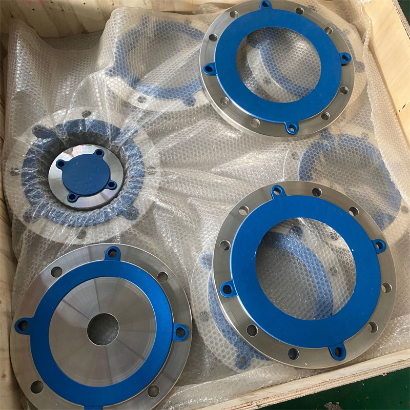
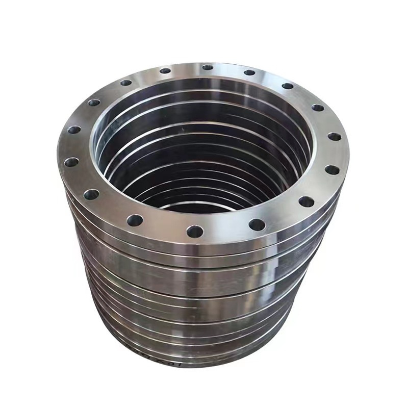
310S Stainless Steel Flange
The 310S stainless steel flange is a highly durable and heat-resistant pipe fitting commonly used in applications that require excellent performance under high-temperature conditions. Here is an introduction to the product:
Material and Heat Resistance: The 310S stainless steel flange is made from high-quality 310S stainless steel, which is an austenitic heat-resistant alloy. This grade of stainless steel offers exceptional resistance to high temperatures, making it suitable for use in environments where heat and thermal cycling are present. It provides excellent oxidation resistance, ensuring reliability even in extreme temperature conditions.
Types and Configurations: The 310S stainless steel flange comes in various types and configurations to meet specific industry requirements. Common types include slip-on flanges, weld neck flanges, blind flanges, and threaded flanges. These options provide flexibility in connecting pipes or valves, allowing for efficient installation and maintenance.
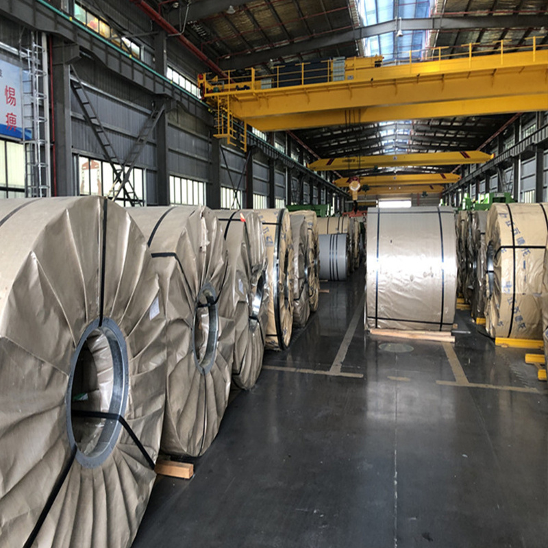
Sizes and Specifications: The dimensions and specifications of the 310S stainless steel flange can be customized to fit different piping systems. It is available in a range of sizes, catering to small, medium, and large diameter pipes, ensuring compatibility with various industrial setups.
Connection Methods: The 310S stainless steel flange can be easily connected to pipes or valves using welding techniques such as TIG (tungsten inert gas) welding or MIG (metal inert gas) welding. Additionally, it can also be threaded onto pipes or joined using socket weld connections. These methods ensure strong and leak-free connections, guaranteeing the integrity of the overall system under high-temperature conditions.
Applications: The 310S stainless steel flange finds extensive application in industries such as petrochemical, power generation, furnace manufacturing, and heat treatment. Its outstanding heat resistance, high strength, and excellent corrosion resistance make it suitable for critical applications involving elevated temperatures, thermal cycling, and corrosive environments. It is commonly used in heat exchangers, boilers, furnaces, and other equipment where withstanding high temperatures is crucial.
In summary, the 310S stainless steel flange is a durable and heat-resistant pipe fitting that excels in high-temperature applications. Its exceptional heat resistance, versatility in types and sizes, and ease of connection make it reliable and efficient. It is widely utilized in industries such as petrochemical, power generation, furnace manufacturing, and heat treatment, where its ability to withstand extreme temperatures and corrosive environments is highly valued.
| 310S Stainless Steel Flange Chemical Compositions |
| Grade | C | Mn | P | S | Si | Cr | Ni |
| 310S | ≤0.08 | ≤2.0 | ≤0.045 | ≤0.03 | ≤1.50 | 24.0-26.0 | 19.0-22.0 |
| Parameter | Description |
| Material | 310S stainless steel |
| Size Range | 1/2 inch - 36 inch |
| Pressure Class | 150 pounds, 300 pounds, 600 pounds |
| Flange Face Type | Raised face (RF), Flat face (FF), Ring type joint (RTJ) |
| Flange Standard | ANSI B16.5, ASME B16.47, DIN, EN, JIS |
| Temperature Range | -200°C to +1150°C |
| Suitable Media | High-temperature gases, Corrosive fluids, Chemicals, etc. |
| Application Areas | Petrochemical industry, Power plants, Heat treatment facilities, Oil and gas industry, etc. |

| ANSI, ASME, ASA, B16.5 150lb/sq.in. WELDING NECK FLANGE RF | |||||||||||
| ø | D | b | g | m | a | J* | h | k | Holes | l | Kg. |
| 1/2" | 88,9 | 11,1 | 34,9 | 30,2 | 21,3 | 15,7 | 47,6 | 60,3 | 4 | 15,9 | 0,500 |
| 3/4" | 98,4 | 12,7 | 42,9 | 38,1 | 26,7 | 20,8 | 52,4 | 69,8 | 4 | 15,9 | 0,700 |
| 1" | 107,9 | 14,3 | 50,8 | 49,2 | 33,5 | 26,7 | 55,6 | 79,4 | 4 | 15,9 | 1,100 |
| 1 1/4" | 117,5 | 15,9 | 63,5 | 58,8 | 42,2 | 35,1 | 57,1 | 88,9 | 4 | 15,9 | 1,500 |
| 1 1/2" | 127,0 | 17,5 | 73,0 | 65,1 | 48,3 | 40,9 | 61,9 | 98,4 | 4 | 15,9 | 1,800 |
| 2" | 152,4 | 19,0 | 92,1 | 77,8 | 60,3 | 52,6 | 63,5 | 120,6 | 4 | 19,0 | 2,700 |
| 2 1/2" | 177,8 | 22,2 | 104,8 | 90,5 | 73,1 | 62,7 | 69,8 | 139,7 | 4 | 19,0 | 4,400 |
| 3" | 190,5 | 23,8 | 127,0 | 107,9 | 88,9 | 78,0 | 69,8 | 152,4 | 4 | 19,0 | 5,200 |
| 3 1/2" | 215,9 | 23,8 | 139,7 | 122,2 | 101,6 | 90,2 | 71,4 | 177,8 | 8 | 19,0 | 6,400 |
| 4" | 228,6 | 23,8 | 157,2 | 134,9 | 114,3 | 102,4 | 76,2 | 190,5 | 8 | 19,0 | 7,500 |
| 5" | 254,0 | 23,8 | 185,7 | 163,5 | 141,2 | 128,3 | 88,9 | 215,9 | 8 | 22,2 | 9,200 |
| 6" | 279,4 | 25,4 | 215,9 | 192,1 | 168,4 | 154,2 | 88,9 | 241,3 | 8 | 22,2 | 11,000 |
| 8" | 342,9 | 28,6 | 269,9 | 246,1 | 219,1 | 202,7 | 101,6 | 298,4 | 8 | 22,2 | 18,300 |
| 10" | 406,4 | 30,2 | 323,8 | 304,8 | 273,0 | 254,5 | 101,6 | 361,9 | 12 | 25,4 | 25,000 |
| 12" | 482,6 | 31,7 | 381,0 | 365,1 | 323,8 | 304,8 | 114,3 | 431,8 | 12 | 25,4 | 39,000 |
| 14" | 533,4 | 34,9 | 412,7 | 400,0 | 355,6 | 336,5 | 127,0 | 476,2 | 12 | 28,6 | 51,000 |
| 16" | 596,9 | 36,5 | 469,9 | 457,2 | 406,4 | 387,3 | 127,0 | 539,7 | 16 | 28,6 | 60,000 |
| 18" | 635,0 | 39,7 | 533,4 | 504,8 | 457,2 | 438,1 | 139,7 | 577,8 | 16 | 31,7 | 71,000 |
| 20" | 698,5 | 42,9 | 584,2 | 558,8 | 508,0 | 488,9 | 144,5 | 635,0 | 20 | 31,7 | 88,000 |
| 22" | 749,3 | 46,0 | 641,2 | 609,6 | 558,8 | 539,7 | 149,2 | 692,1 | 20 | 34,9 | 102,000 |
| 24" | 812,8 | 47,6 | 692,1 | 663,6 | 609,6 | 590,5 | 152,4 | 749,3 | 20 | 34,9 | 119,000 |
| *The data "J" corresponds to the STD schedule | |||||||||||
| ANSI, ASME, ASA B16.5 300lb/sq.in. WELDING NECK FLANGE RF | |||||||||||
| ø | D | b | g | m | a | J* | h | k | Holes | l | Kg. |
| 1/2" | 95,2 | 14,3 | 34,9 | 38,1 | 21,3 | 15,7 | 52,4 | 66,7 | 4 | 15,9 | 0,900 |
| 3/4" | 117,5 | 15,9 | 42,9 | 47,6 | 26,7 | 20,8 | 57,1 | 82,5 | 4 | 19,0 | 1,500 |
| 1" | 123,8 | 17,5 | 50,8 | 54,0 | 33,5 | 26,7 | 61,9 | 88,9 | 4 | 19,0 | 1,900 |
| 1 1/4" | 133,3 | 19,0 | 63,5 | 63,5 | 42,2 | 35,1 | 65,1 | 98,4 | 4 | 19,0 | 2,600 |
| 1 1/2" | 155,6 | 20,6 | 73,0 | 69,8 | 48,3 | 40,9 | 68,3 | 114,3 | 4 | 22,2 | 3,300 |
| 2" | 165,1 | 22,2 | 92,1 | 84,1 | 60,3 | 52,6 | 69,8 | 127,0 | 8 | 19,0 | 3,600 |
| 2 1/2" | 190,5 | 25,4 | 104,8 | 100,0 | 73,1 | 62,7 | 76,2 | 149,2 | 8 | 22,2 | 5,400 |
| 3" | 209,5 | 28,6 | 127,0 | 117,5 | 88,9 | 78,0 | 79,4 | 168,3 | 8 | 22,2 | 7,400 |
| 3 1/2" | 228,6 | 30,2 | 139,7 | 133,3 | 101,6 | 90,2 | 81,0 | 184,1 | 8 | 22,2 | 8,900 |
| 4" | 254,0 | 31,7 | 157,2 | 146,0 | 114,3 | 102,4 | 85,7 | 200,0 | 8 | 22,2 | 11,900 |
| 5" | 279,4 | 34,9 | 185,7 | 177,8 | 141,2 | 128,3 | 98,4 | 234,9 | 8 | 22,2 | 16,000 |
| 6" | 317,5 | 36,5 | 215,9 | 206,4 | 168,4 | 154,2 | 98,4 | 269,9 | 12 | 22,2 | 20,200 |
| 8" | 381,0 | 41,3 | 269,9 | 260,3 | 219,1 | 202,7 | 111,1 | 330,2 | 12 | 25,4 | 31,000 |
| 10" | 444,5 | 47,6 | 323,4 | 320,7 | 273,0 | 254,5 | 117,5 | 387,3 | 16 | 28,6 | 44,300 |
| 12" | 520,7 | 50,8 | 381,0 | 374,6 | 323,8 | 304,8 | 130,2 | 450,8 | 16 | 31,7 | 64,000 |
| 14" | 584,2 | 54,0 | 412,7 | 425,4 | 355,6 | 336,5 | 142,9 | 514,3 | 20 | 31,7 | 88,000 |
| 16" | 647,7 | 57,1 | 469,9 | 482,6 | 406,4 | 387,3 | 146,0 | 571,5 | 20 | 34,9 | 113,000 |
| 18" | 711,2 | 60,3 | 533,4 | 533,4 | 457,2 | 438,1 | 158,7 | 628,6 | 24 | 34,9 | 134,000 |
| 20" | 774,7 | 63,5 | 584,2 | 587,4 | 508,0 | 488,9 | 161,9 | 685,8 | 24 | 34,9 | 171,000 |
| 22" | 838,2 | 66,7 | 641,2 | 641,2 | 558,8 | 539,7 | 165,1 | 742,9 | 24 | 41,3 | 195,000 |
| 24" | 914,4 | 69,8 | 692,1 | 701,7 | 609,6 | 590,5 | 168,3 | 812,8 | 24 | 41,3 | 238,000 |
| *The data "J" corresponds to the STD schedule | |||||||||||
| ANSI/ASME/ASA B16.5 600lb/sq.in. WELDING NECK FLANGE RF | |||||||||||
| ø | D | b | g | m | a | J* | h | k | Holes | l | Kg. |
| 1/2" | 95,2 | 14,3 | 34,9 | 38,1 | 21,3 | 15,7 | 52,4 | 66,7 | 4 | 15,9 | 0,900 |
| 3/4" | 117,5 | 15,9 | 42,9 | 47,6 | 26,7 | 20,9 | 57,1 | 82,5 | 4 | 19,0 | 1,500 |
| 1" | 123,8 | 17,5 | 50,8 | 54,0 | 33,5 | 26,7 | 61,9 | 88,9 | 4 | 19,0 | 1,900 |
| 1 1/4" | 133,3 | 20,6 | 63,5 | 63,5 | 42,2 | 35,0 | 66,7 | 98,4 | 4 | 19,0 | 2,600 |
| 1 1/2" | 155,6 | 22,2 | 73,0 | 69,8 | 48,3 | 40,9 | 69,8 | 114,3 | 4 | 22,2 | 3,300 |
| 2" | 165,1 | 25,4 | 92,1 | 84,1 | 60,3 | 52,6 | 73,0 | 127,0 | 8 | 19,0 | 4,700 |
| 2 1/2" | 190,5 | 28,6 | 104,8 | 100,0 | 73,1 | 62,7 | 79,4 | 149,2 | 8 | 22,2 | 6,500 |
| 3" | 209,5 | 31,7 | 127,0 | 117,5 | 88,9 | 78,0 | 82,5 | 168,3 | 8 | 22,2 | 8,700 |
| 3 1/2" | 228,6 | 34,9 | 139,7 | 133,3 | 101,6 | 90,1 | 85,7 | 184,1 | 8 | 25,4 | 11,200 |
| 4" | 273,0 | 38,1 | 157,2 | 152,4 | 114,3 | 102,4 | 101,6 | 215,9 | 8 | 25,4 | 18,100 |
| 5" | 330,2 | 44,4 | 185,7 | 188,9 | 141,2 | 128,2 | 114,3 | 266,7 | 8 | 28,6 | 30,500 |
| 6" | 355,6 | 47,6 | 215,9 | 222,2 | 168,4 | 154,2 | 117,5 | 292,1 | 12 | 28,6 | 36,200 |
| 8" | 419,1 | 55,6 | 269,9 | 273,0 | 219,1 | 202,7 | 133,3 | 349,2 | 12 | 31,7 | 56,500 |
| 10" | 508,0 | 63,5 | 323,8 | 342,9 | 273,0 | 254,5 | 152,4 | 431,8 | 16 | 34,9 | 91,000 |
| 12" | 558,8 | 66,7 | 381,0 | 400,0 | 323,8 | 304,8 | 155,6 | 488,9 | 20 | 34,9 | 105,000 |
| 14" | 603,2 | 69,8 | 412,7 | 431,8 | 355,6 | * | 165,1 | 527,0 | 20 | 38,1 | 125,000 |
| 16" | 685,8 | 76,2 | 469,9 | 495,3 | 406,4 | 177,8 | 603,2 | 20 | 41,3 | 178,000 | |
| 18" | 742,9 | 82,5 | 533,4 | 546,1 | 457,2 | 184,1 | 654,0 | 20 | 44,4 | 261,000 | |
| 20" | 812,8 | 88,9 | 584,2 | 609,6 | 508,0 | 190,5 | 723,9 | 24 | 44,4 | 268,000 | |
| 22" | 869,9 | 95,2 | 641,2 | 666,7 | 558,8 | 196,8 | 777,9 | 24 | 47,6 | 328,000 | |
| 24" | 939,8 | 101,6 | 692,1 | 717,5 | 609,6 | 203,2 | 838,2 | 24 | 50,8 | 380,000 | |
| *The data "J" corresponds to the STD schedule | |||||||||||
| To be specifiedby customer | |||||||||||